Boiler Measurement Guide
Published: June 24, 2020
By: Phillip Chao, PhD | Applied Research Scientist, Peter Phung, Tom Lui | Interns, Duncan Prahl, RA, AIA | Sr. Applied Research Scientist
Reviewed by: Jillian Panagakos | Jr. Engineer, Honey Berk, LEED AP O&M,CMVP | Managing Director
Helpful Resources
Download this Guide
DownloadGeneral System Overview
This guide describes the measurement approach for quantifying avoided energy use associated with retrofitting existing boiler systems with more efficient boilers.
Safety
This guide does not cover health and safety aspects of the collection of measurements at facilities. There are many hazards that exist in facilities surrounding the collection of measurements, including but not limited to: electrical safety, fall protection, personal protective equipment, control of hazardous energy (lock out/tag out), confined space, respiratory protection, and machine safeguarding. Part of the measurement planning process must include the identification and mitigation of these and other hazards. The implementation of a measurement strategy and installation of measurement equipment should be performed by qualified personnel.
Description of System
The following sections provide background information on the components of a boiler system. If you are already familiar with the system, you may skip to the Measurement Description for System section.
System Overview
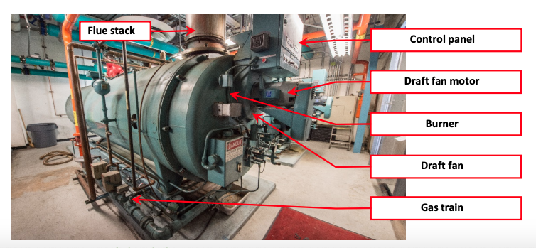
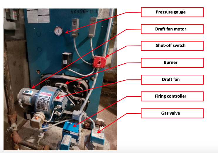
A boiler system is comprised of a closed pressure vessel, exhaust vents for flue gases, a motor for air intake, and a burner to initiate combustion. Two examples of commercial boilers are shown in Figures 1 and 2.
Key Variables Associated with Calculating Energy Consumption of a Boiler System
The primary energy source for a boiler system is fuel, which is measured in the respective fuel unit type (e.g., gallons, cubic feet). The relevant variables used to characterize the fuel consumption of a boiler system are:
- Operating Schedule
- Fuel Type
- Fuel Consumption
- OAT
Operating Characteristics
From the perspective of energy consumption, boiler systems have two operating modes – modulating and non-modulating. This guide is intended to measure boiler fuel use for a non-modulating boiler system. The approach for a modulating boiler system is a bit more complex, as the firing rate modulates to match the boiler output to the building heating load which results in changes in fuel and electricity consumption rate. Alternatively, a non modulating boiler will turn on and off based on the system’s internal pressure and control settings; this often leads to more on-off cycles.
It is important to discuss with the building operator the operating characteristics of the boiler to
determine how the boiler is being run. Many buildings have multiple boilers and a variety of controllers that may include: OAT reset, modulating firing rate, fixed or staged firing rate, multiple modular boilers programmed to fire in sequence, differently sized boilers for use at different times of the year (e.g., summer boiler for DHW), dual fuel configurations, or other. It is important to characterize the type of system, any associated controllers, and the way in which boiler is actually operated, in order to reasonably quantify an estimate of annual consumption.
Scope of This Guide
This guide describes how to measure and analyze the annual energy consumption of two ECMs that are relevant to boiler systems:
- Boiler Replacement: Older low-efficiency or poorly operating boilers can be replaced with higher efficiency, more responsive equipment. This may include resizing boilers to enable the modulation to more closely match the heating load, or to provide domestic hot water more efficiently when heating is not needed.
- Boiler Tuning: A boiler that is not tuned regularly will likely run less effectively than designed. Boiler tuning typically increases efficiency and thereby reduces fuel consumption and GHG emissions.
This guide is designed to assist in gathering both pre- and post-retrofit data for the fuel consumption of a boiler system used for space heating. As such, a primary goal is to describe the data that should be collected through measurements and the appropriate equipment to perform those measurements. Guidance is provided for measuring boiler system runtime and fuel consumption. Upgrades to hot water circulating pumps and draft fans are not covered in this guide.
In addition to facilities with large boilers, this guide may also be used at facilities that are equipped with many small boilers that are sequenced to fire individually as the heating load increases. These systems may have been modified over time and therefore not operating as originally intended. Boilers may be grouped to fire together instead of sequentially, non-operable boilers may be taken offline, or boilers sequence may be altered to rotate for even wear. A customized measurement strategy will likely be necessary for these situations.
The measurement strategies in this guide may be used on dual fuel boilers, however care must be taken to have proper recording equipment for measurements of both the natural gas and fuel oil consumption. This guide does not explicitly provide a methodology for measuring the aggregate fuel use of a dual fuel system; instead, each measurement technique should be individually applied and engineering judgement used in the interpretation of results.
Finally, if an estimate of boiler fuel consumption is needed for domestic hot water purposes, simply apply the measurement techniques in this guide for several weeks during the non-heating season, and derive an average daily or weekly fuel consumption amount, since domestic hot water consumption usually does not have any correlation to OAT.
Measurements
Measurement Approach
This guide is focused on characterizing the annual fuel consumption for a boiler system based on OAT and day-of-week operating schedule. The measurement boundary of the system is defined simply as the fuel used by the boiler as reflected in the operational runtime and sequencing of one or more boilers in a facility. Figure 3 and Figure 4 illustrate the measurement boundaries used within the confines of this guide for a natural gas-fired boiler.
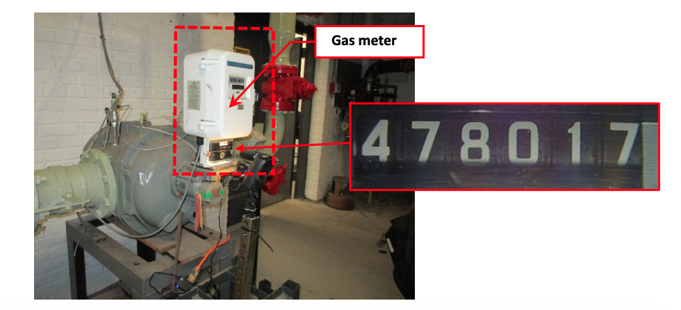
The first step is to determine how fuel measurements are to be taken. Figure 5 depicts a decision tree that can be used to evaluate options for fuel data collection. CUNY BPL has used a time lapse camera to record natural gas meter readings (where the camera can be set up in a secure location), and has also developed an automated method to read natural gas meters with digital readouts similar to the one shown in Figure 4.
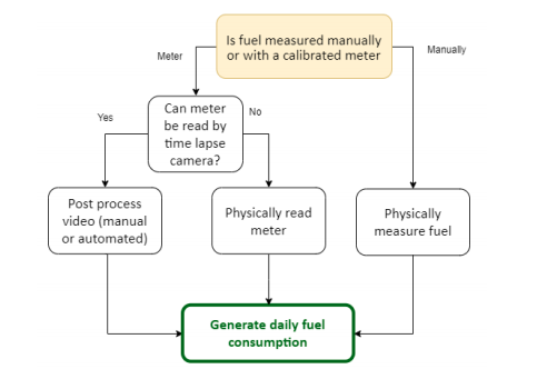
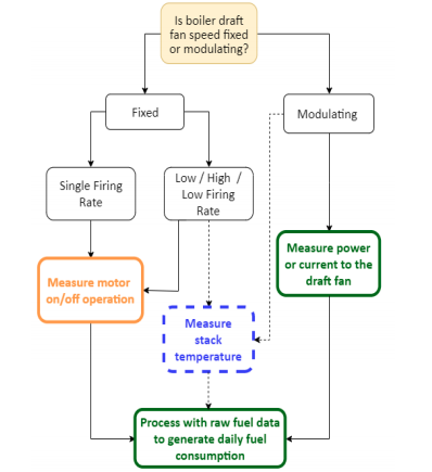
Figure 6 depicts a decision tree that can be used to determine which measurement strategy to apply to a specific system based on system configuration and components.
The measurements are designed to quantify fuel use per day using boiler runtime per day as a proxy for boiler firing; boiler start and stop times per day (if the boiler is set back or manually operated by a building operator); and if there are multiple boilers, which one is running as the “lead” or primary boiler and which is the “lag” or second-stage firing boiler.
Ideally, fuel consumption is measured using a calibrated meter. Inline meters that directly measure the flow of the fuel being used are best, however in many cases these are impractical to add on to individual or multiple boilers. Ultrasonic meters are available for non-intrusive measurement; however, many fuel oil systems continuously circulate, so direct measurement of the oil flow through the pipe is not representative of the actual consumption of the boiler. Natural gas is typically metered by the utility, and in most facilities there is either a dedicated meter for the boilers or the boilers are the dominant use of natural gas. Meter location will influence the ability to implement some of the measurement techniques listed below.
Given the number of variables, a number of strategies are listed below. These are based on either taking manual direct measurements or recording utility meter operation over time and translating that into a data file.
It is strongly recommended, in the implementation of boiler ECMs in this guide, to specify a system that enables trend-logging of the firing rate, runtime, and fuel consumption as part of the retrofit. The boiler control system or a building automation system (BAS) can then be used to record long-term measurement of post-retrofit operation to estimate annual consumption.
Sampling
Since there are usually no more than three boilers associated with any given project, sampling is not recommended. In addition, multiple boiler systems are typically cycled by building operations staff to even out overall runtime and the lead/lag use of the boilers. If a rigorous sampling plan is needed, Bonneville Power Administration2 has developed an excellent reference for guidance.
Measurement Strategies
To develop a reasonable estimate for the annual consumption of a boiler system, daily fuel use must be quantified and correlated to the operational schedule of the facility and OAT. This requires measurement of the daily operation of the boiler draft fan(s), daily fuel consumption of the boiler(s), and average daily OAT.
Measure Motor On/Off Operation
This strategy is for single-speed fans. Single-speed fans may be installed on modulating boilers, where the air mixture is controlled by the relative position of the air damper at less than high fire. Draft fans are typically turned on shortly before a boiler fires (pre-purge) and turned off slightly after the burner has stopped firing (post-purge). The draft fan on-off cycle is not an exact measure of the firing time, however the duration of the pre- and post-purge cycles are usually the same regardless of the length of time the boiler fires. A motor on/off data logger is used to track the operating schedule, and identifies the lead and lag boiler, the sequence of boiler rotation over time (if boiler operations are rotated), and if the boiler is frequently turning on and off (i.e., short-cycling).
For each single-speed draft fan motor, the following parameter should be measured:
- Fan motor runtime
Motor on/off loggers only sense the magnetic field of motors running at 60Hz. If it is not possible to determine whether the draft fan has a single-speed 60Hz motor (e.g., through physical observation of the system, an interview with the building operator, or review of as-built drawings) it is best to derive runtime by using the next measurement strategy.
Measure Draft Fan Motor Current or Power
When the power draw of the draft fan motor is varied (i.e., modulating or running at multiple fixed speeds) the measurement approach needs to characterize the range of operation and how it varies over time. While motor on/off loggers do not sense the magnetic field of motors running below 60 Hz, measuring the power or current to the motor captures both the runtime of the boiler and the relative speed of the motor, which is an indication of the firing rate.
Measure Stack Temperature
If a more detailed evaluation of the relative firing rate of a low/high/low or modulating firing rate boiler with a single-speed fan is needed, measuring the flue stack temperature in conjunction with the motor runtime can provide insight into the hourly firing rate of the boiler system. However, it is not necessary for estimating annual fuel consumption.
Measure Daily Fuel Consumption
Given the difficulty of installing equipment to directly measure fuel consumption, two general strategies are recommended. First, CUNY BPL has been successful processing time lapse video from a gas meter digital readout into a time-stamped data file. The video can also be manually translated into a spreadsheet. If this is not achievable, the second strategy is the time-honored tradition of “dipping the tank” for oil or manually logging a daily reading of the gas meter.
Measurement Tools and Equipment
The measurements in this guide can be performed with the equipment listed in Table 1; more detailed descriptions have been provide in Table 2. NYC agency employees can borrow the recommended equipment from the NYC Energy Tools equipment library, and have it delivered to their facility. Third-party M&V consultants and others can use this equipment list as guidance, recognizing that many manufacturers make comparable equipment. Inclusion on the list in Table 1 or Table 2 should not be construed as an endorsement of these manufacturers.
| Measurement | Units | Tool | Equipment |
|---|---|---|---|
| True RMS Energy | kWh | Data-logging Power Meter and Current Transformers | DENT ELITEpro XC Portable Power Data Logger (EXCUNC) Dent 16” RoCoil Flexible Rope Current Transformers (CT-R16-A4-U) |
| Burner Motor On/Off & Runtime | Seconds/hour & % | Motor On/Off Data Logger | Onset HOBO Motor On/Off Data Logger (UX9- or UX90-004) |
| Fuel flow rate (GPM/CFM) | GPD/CFD | Time lapse camera | Brinno TLC200 Pro |
| Flue Stack Temperature | °F | Data Logger and Stack Temperature Sensor Thermocouple | Onset HOBO 4-Channel Thermocouple Logger (UX120-014M) Onset HOBO Type K 12″ Probe Thermocouple Sensor |
| OAT | °F | Weatherproof Temperature/Relative Humidity Data Logger | Onset HOBO Temperature/Relative Humidity Weatherproof Data Logger (MX2301) |
| Equipment | Description |
|---|---|
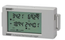 4-channel thermocouple data logger (UX120-014M) | Used to record flue gas temperatures to assess firing rate of a modulating boiler. Can accept up to four J, K, T, E, R, S, B, or N type probes. In addition the logger features an internal sensor for logging ambient temperatures. Not a required measurement. |
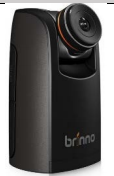 | Takes pictures with respect to a time interval set by the user. Stores all of the pictures that the camera has taken in a video file that can be used to obtain measurement data for whatever the camera was pointed at. Should only be used in a secure location. |
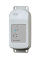 Onset HOBO Temp/RH Data Logger-mx2301 | Records outdoor air temperature and relative humidity using internal sensors. Requires HOBOware software and a USB connection cable for programming and downloading data files. |
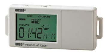 Onset HOBO Motor On/Off Data Logger (UX90-004) | Records when a motor is on and off, as well as runtime. Requires HOBOware software and a USB connection cable for programming and downloading data files. |
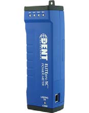 DENT ELITEproXC Portable Power Data Logger (EXCUNC) 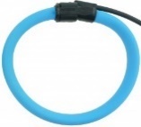 DENT 16” RoCoil Flexible Rope Current Transformers (CT-R16-A4-U) | Provides a measurement of true RMS power from voltage and current inputs and records long-term power (kW) and energy (kWh) measurements. Requires ELOG19 software and a USB connection cable for programming and downloading data files. |
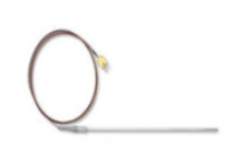 Onset HOBO Type K 12″ Probe Thermocouple Sensor | Used to measure flue gas temperature if needed. Converts the measurement to a signal that the 4-Channel Thermocouple Logger (UX120-014M) can record. Not a required measurement. |
Measurement Strategies
The following instructions have been developed for each measurement strategy discussed in this guide. While these instructions are reasonably detailed, certain aspects of each strategy may need to be modified based on the specific system configuration at each facility. Early surveying of the facility is useful when tailoring each strategy to unique site conditions.
The measurement recommendations reference supplementary equipment guides, which can be found in Appendix A.
• A.1: Onset HOBO Motor On/Off Data Logger (UX90-004)
• A.3: DENT ELITEpro XC Portable Power Data Logger
• A.7: Onset HOBO Temperature/RH Data Logger (MX2301)
• A.11: Brinno TLC200 Pro Time Lapse Camera
Measure Draft Fan Motor On/Off Operation
This measurement approach is intended for single-speed, fixed firing rate boiler system configurations.
STEP 1: Preparation for Data Acquisition
- Confirm site conditions and locations where data acquisition equipment will be placed.
- Obtain measurement equipment from NYC Energy Tools:
- Onset HOBO Motor On/Off Data Logger (UX90-004)
- Fluke 345 Power Quality Clamp Meter
- Refer to A.1: Onset HOBO Motor On/Off Data Logger (UX-90-004)
- Set up and deploy data logger per the instructions in sections A.1.1 to A.1.3.
STEP 2: Installation at the Site
- Implement appropriate safety procedures.
- Refer to A.1: Onset HOBO Motor On/Off Data Logger (UX90-004)
- Install the motor on/off logger in the selected location and be sure the logger passes the calibration with the motor running per the instructions in sections A.1.4 and A.1.5.
- Initial field setup is now complete.
STEP 3: Verify Data is Being Collected
- Implement appropriate safety procedures.
- If possible, wait for the first recording period to pass during the installation at site; if not, return to the site as soon as possible to retrieve data from the logger to verify data collection. Do not remove the logger from the equipment.
- Refer to Appendix A.1: Onset HOBO Motor On/Off Data Logger (UX90-004)
- Confirm that the logger is collecting data and the system operation is being recorded per the instructions in A1.6. Be careful not to stop the logger when downloading data.
- It is recommended that this step be repeated periodically during the measurement period.
STEP 4: Retrieve Data Acquisition Equipment and Download Data
- Implement appropriate safety procedures.
- Refer to Appendix A.1: Onset HOBO Motor On/Off Data Logger (UX90-004)
- Confirm that the logger has collected the required operational data per the instructions in section A.1.6. Do not yet remove the logger from the equipment. Be careful not to stop the logger when downloading data.
- Once data acquisition has been confirmed, stop the logger per the instructions in section A.1.7.
- Remove the data logger and return to NYC Energy Tools.
Measure Draft Fan Motor Power
This approach should be used in a boiler with a variable speed fan and burner. Post processing of data is needed to convert hourly power as a percentage of full fire operation to an equivalent gross daily firing rate. Workbooks for this conversion have not been fully developed.
STEP 1: Preparation for Data Acquisition
- Confirm site conditions and locations where data acquisition equipment will be placed.
- Obtain measurement equipment from NYC Energy Tools:
- DENT ELITEpro XC Portable Power Data Logger – (EXCUNC) with 16” Flexible Current Transformers (CTs) (DENT CT-R16-A4-U)
- Obtain measurement equipment from NYC Energy Tools:
- Refer to Appendix A.3: DENT ELITEpro XC Portable Power Data Logger
- Set up and initialize the DENT logger per the instructions in section A.3.1.
- Refer to Appendix A.3: DENT ELITEpro XC Portable Power Data Logger
- Set up and initialize the DENT logger per the instructions in sections A.3.1.
STEP 2: Installation at the Site
- Implement appropriate safety procedures.
- Appendix A.3: DENT ELITEpro XC Portable Power Data Logger
- Install the DENT ELITEpro XC Portable Power Data Logger using sections A.3.2 to A.3.3 as guidance. Keep the computer connected to the logger so the readings can be seen in real time.
- Ask the facility representative to operate the boiler at four or five firing rates (e.g minimum ~30%, ~60% maximum) for three to five minutes at each rate.
- Confirm the readings have been recorded by DENT ELITEproXC Portable Power data logger.
- Initial field setup is now complete.
STEP 3: Verify Data is Being Collected
- Implement appropriate safety procedures.
- If possible, wait for the first recording period to pass during the installation at site; if not, return to the site as soon as possible to retrieve data from the logger to verify data collection. Do not remove the logger from the equipment.
- Refer to Appendix A.3: DENT ELITEproXC Portable Power Data Logger
- Confirm that the DENT ELITEproXC Portable Power Data Logger is collecting data and that system operation is being recorded per the instructions in section A.3.4. Be careful not to stop the meter when downloading data.
- It is recommended that this step be repeated periodically during the measurement period.
STEP 4: Retrieve Data Acquisition Equipment and Download Data
- Implement appropriate safety procedures.
- Refer to Appendix A.3: DENT ELITEproXC Portable Power Data Logger
- Confirm that the DENT ELITEproXC Portable Power Data Logger has collected the required data per the instructions in section A.3.4. Do not yet remove the meter from the equipment. Be careful not to stop the meter when downloading data.
- Once data acquisition has been confirmed, stop the logger per the instructions in section A.3.5.
- Remove the data logger and return to NYC Energy Tools.
Measure Daily Fuel Consumption with Time Lapse Camera
This measurement approach provides a non-intrusive method of obtaining the natural gas consumption of a boiler with the use of a Brinno TLC200 Pro Time Lapse Camera. The camera records time-lapse photos of the natural gas meter, which are stored in an AVI file from which meter readings can be extracted and analyzed for the purposes of this M&V guide.
STEP 1: Preparation for Data Acquisition
- Confirm site conditions and locations where data acquisition equipment will be placed.
- Obtain measurement equipment from NYC Energy Tools:
- Brinno TLC200 Pro Time Lapse Camera
- Refer to Appendix A.11 Brinno TLC200 Pro Time Lapse Camera
- Set up and deploy camera per the instructions in section A.11.1.
STEP 2: Installation at the Site
- Implement appropriate safety procedures.
- Refer to Appendix A.11 Brinno TLC200 Pro Time Lapse Camera
- Install the camera at the field site by following the steps outlined in section A.11.2.
- Initial field setup is now complete.
STEP 3: Verify Data is Being Collected
- Implement appropriate safety procedures.
- Refer to the last step of Appendix A.11.2 and Appendix A.11.3.
- Confirm that the logger is collecting data. The LCD screen of the Brinno TLC200 Pro Time Lapse Camera should have the word “REC” right under the preview screen, which means the camera is taking time-lapse photos.
- It is recommended that this step be repeated periodically during the measurement period.
- Ensure that the meter window is free of any dirt or obstructions during the periodic checkup.
STEP 4: Retrieve Data Acquisition Equipment and Download Data
- Implement appropriate safety procedures.
- Refer to Appendix A.11.4
- Confirm that the logger has collected the required operational data per the instructions in section A.11.4. Follow that section to view the contents of the SD card on your computer. Do not yet remove the camera from the equipment.
- Once data acquisition has been confirmed, shut off the camera.
- Process video file manually or request CUNY BPL support in translation of the video to a data file.
- Remove the camera and return to NYC Energy Tools.
Manually Measure Daily Fuel Consumption
Tools from NYC Energy Tools are usually not needed in the case of obtaining the fuel consumption from dipstick readings or manual meter readings. Dipstick or meter readings should be conducted daily by the building personnel and the fuel levels recorded in a log.
- Three headings are needed for the log:
- Calendar date
- Time in hours (0 – 23, where 0 = 12:00 a.m. to 12:59 a.m.)
- Fuel consumed since last reading in gallons or cubic feet
Measure Outdoor Air Temperature
STEP 1: Preparation for Data Acquisition
- Confirm site conditions and locations where data acquisition equipment will be placed.
- Obtain measurement equipment from NYC Energy Tools:
- Onset HOBO Temperature/Relative Humidity Weatherproof Data Logger (MX2301)
- Obtain measurement equipment from NYC Energy Tools:
- Refer to Appendix A.7: Onset HOBO Temperature/Relative Humidity Weatherproof Data Logger (MX2301)
- Set up and initialize the Temperature/Relative Humidity Weatherproof Data Logger, per the instructions in sections A.7.1 through A.7.3.
STEP 2: Installation at the Site
- Implement appropriate safety procedures.
- Install the Temperature/Relative Humidity Weatherproof Data Logger using section A.7.4 as guidance.
- Initial field setup is now complete.
STEP 3: Verify Data is Being Collected
- Implement appropriate safety procedures.
- If possible, wait for the first recording period to pass during the installation at site; if not, return to the site as soon as possible to retrieve data from the logger to verify data collection. Do not remove the logger from the equipment.
- Refer to Appendix A.7: Onset HOBO Temperature/Relative Humidity weatherproof Data Logger (MX2301)
- Confirm that the Onset HOBO Temperature/Relative Humidity weatherproof Data Logger (MX2301) is collecting data and that system operation is being recorded per the instructions in sections A.7.5, respectively. Be careful not to stop the loggers when downloading data.
- It is recommended that this step be repeated periodically during the measurement period.
STEP 4: Retrieve Data Acquisition Equipment and Download Data
- Implement appropriate safety procedures.
- Refer to Appendix A.7: Onset HOBO Temperature/Relative Humidity weatherproof Data Logger (MX2301)
- Confirm that the Temperature/Relative Humidity Weatherproof Data Logger (MX2301) has collected the required data per the instructions in sections A.7.5. Do not yet remove the loggers from the equipment. Be careful not to stop the loggers when downloading data.
- Once data acquisition has been confirmed, stop the loggers per the instructions in section A.7.6.
- Remove the data logger and return to NYC Energy Tools.
Calculation Methodology
Total heating season energy is calculated using the general equation, below:
E=\sum_{n}an * P_i[kW]where,
Eann = annual normalized fuel usage of boiler
an = regression coefficient in fuel use/average daily OAT in °F for 𝑛 day of year
Xn = NOAA CNY OAT for 𝑛 day of year, in °F
b = y-intercept of regression equation
One Microsoft Excel workbook has been developed along with this guide to facilitate the calculation of total annual energy consumption from the measured data:
- 2002_0720_boiler. This workbook assumes that boiler operation for space heating begins when the daily OAT is below 65°F. Fuel consumption readings that are not taken at 12:00 a.m. each day are apportioned by boiler runtime. Measurements of fuel consumption are needed, as is the time the reading was taken, the motor runtime for all operating boilers, and the corresponding average OAT for that day. If the boiler makes both space heat and domestic hot water, this workbook calculates the fuel consumption for both. To calculate only the space heating consumption, separate measurements must be taken during the non-heating season, an average daily fuel consumption for domestic hot water must be derived, and that consumption must then be subtracted from the fuel consumption calculated in the workbook for the number of days the boiler is providing space heat.
Instructions are included in the boiler calculation workbook that detail how to input data and how to interpret and make use of the results. Specific calculation methodologies can be found in Appendix A.14: Boiler Calculations and are captured in the workbook. Click the workbook name to download.
This calculation is based on the daily fuel consumption of the boiler (i.e., from 12:00 a.m. to 11:59 p.m.). Daily fuel readings must be aligned with this time period; if readings cannot be taken at 12:00 a.m. each day, then the following calculations can be used to apportion fuel use per day.
Reporting Recommendations
As part of the documentation of expected avoided energy use, the integration of measurements and calculation methodology discussed in this guide will serve to enhance these projections. To facilitate transparency and data quality control, the following pieces of information should be documented to accompany expected savings calculations:
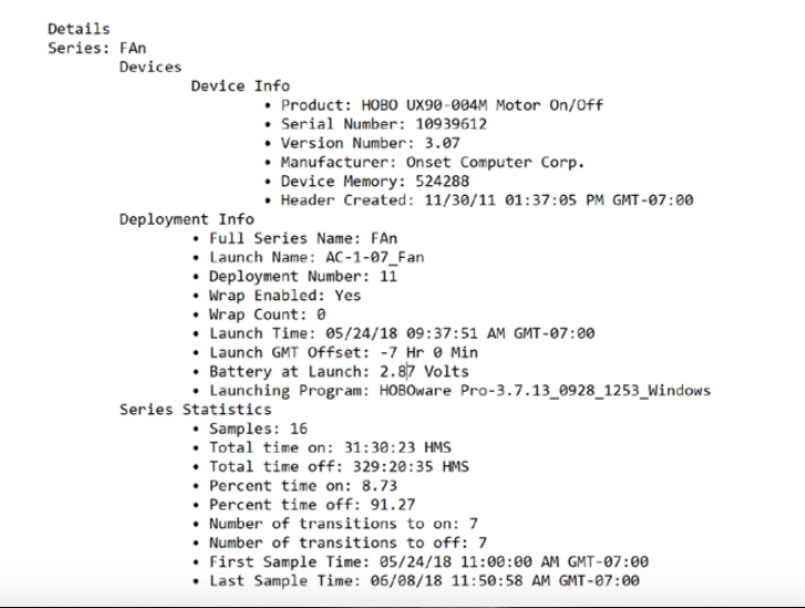
- Measurement tool information and dates of measurement. The HOBOware software records logger information (such as product, serial number, and version number) as well as deployment and measurement dates. To export this information, use the software to open the logger data file, then select “Export Details” from the File menu; this will produce a text file like the one shown in Figure 7. Repeat for all data loggers that were deployed and include all files with the funding application.
- If a BAS was used to collect any of the information discussed in this guide, submit a brief description of the system, including:
- BAS manufacturer and model
- BAS software and version number
- Measurement dates
- Most recent date of sensor calibration (if a sensor was used)
- The completed workbook(s) containing measured data.
It is expected that the user will be responsible for measuring the system of interest and compiling the data input to the calculation tools. The output of these tools can be directly used to satisfy reporting requirements.