Electrical Current
Understand how to perform electrical current measurements. Learn which tools and meter specifications you need to capture valid readings. Follow a clear, step-by-step procedure to take multiple spot measurements and record your data for analysis and use in calculations.
Measurement Overview
What:Long-term measurements of electrical current (Amps) at one-hour intervals.
Why:Provides insight on the operating schedule of the system or component and can be used to calculate energy consumption of the target equipment at the power panel or electrical panelboard.
Duration:The best practice is a minimum of six weeks with data being collected at one-hour intervals; longer measurement periods are encouraged for deeper analysis of the equipment.
When:Measurements should be taken when the system or component is operating under normal conditions.
Type of Measurement:Direct and Proxy.
This technique uses a data logger and current transformers to take long-term measurements of electrical current (Amps) at one-hour intervals. This data provides insight on the operating schedule of the system or component and can be used to calculate energy consumption of the target equipment at the power panel or electrical panelboard. A system or component that is running (i.e., consuming energy) will have high current draw. A system or component that is not running (i.e., has no energy consumption) will have low or no current draw.
Data loggers and current sensors use instantaneous measurements of current over the course of an hour to calculate the average amperage. As such, current data should be recorded as hourly average values, not instantaneous. When taking one-hour measurements, the logger detects current over the course of every hour and store that value. Occasionally, current can fluctuate over a one-hour period (motors turn off or change speed), but the instantaneous current value will not indicate that change.
The duration of the long-term measurement and when to measure is dependent on the system and the operation of the building. The best practice is a minimum of six weeks with data being collected at one-hour intervals; longer measurement periods are encouraged for deeper analysis of the equipment. Measurements should be taken when the system or component is operating under normal conditions.
- Direct: Specifies a quantity of the exact item being measured.
- Proxy: Provides an indication of the system operation but does not directly measure the quantity in question.
Measurement Tools
The measurement tool needed for this procedure is an energy data logger with capacity to measure AC current over time and record measurement data in its internal storage.
Current transformers are sensors that detect the magnetic field induced by an electrical current through a wire. As the current increases or decreases, the magnetic field strength changes, and the current transformers detect this change. The data logger calculates current through the wire based on the signal from the transformers and record the AC current value in its internal storage. A data logger can have multiple current transformers connected to it, allowing a user to measure multiple wires with a single logger.
NYC agency personnel can borrow measurement data loggers, meters, or sensors from our tool library, by selecting tools based on the required measurement duration. See recommended tools found in our library:
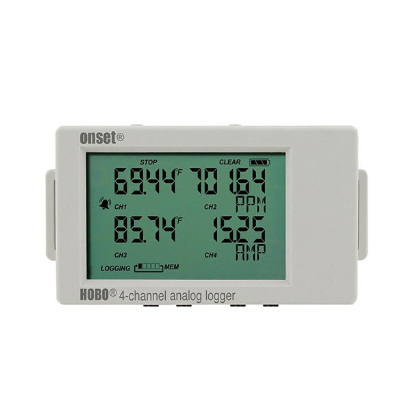
Standalone data logger that monitors up to four external sensors like current transformers.
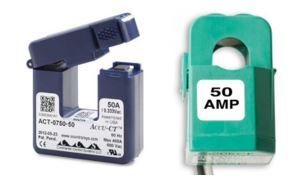
Split-core CTs provide accurate measurements of high alternating current. CTs may be installed without disconnecting wires or interrupting power.
Measurement Steps
Prepare Tools
Use the manufacturer’s software to set up and launch the logger(s). Refer to the equipment’s user manual for detailed setup instructions. Before proceeding, identify the current rating(s) of the wires to be measured to ensure the selection of a properly sized current transformer for this measurement approach. For further guidance on selecting the appropriate current transformer for the target system or component, consult the equipment’s instruction manual.
- Logging interval: 1-hour
- Date and time to start logging
- Date and time to stop logging
- Sampling interval: 1-second
- Value to measure: AC current (Amps)
- Activate input channels of the logger
- Select the current rating of transformers being used
An example of how to setup the Onset HOBO 4-channel analog logger (UX120-006M) is shown in the video below:
Install Tools
- Confirm that the tool is operational.
- Connect the sensors to the data logger.
- Determine whether the distribution system supplies electricity to other loads unrelated to the project to avoid measuring unintended energy consumption.
- Identify the wiring configuration of the distribution system. This will determine how to set up the logger and sensors.
- Based on the wiring configuration and instructions from the equipment’s user manual, install the sensor and logger to measure the current draw by the system. The current transformers are clamps that open and surround the wire, see Figure 2.
- Clamp the sensors around the electrical wires. Make sure they are facing the right direction, or the current may be recorded with negative values.
- Adhere the data logger to the panelboard. Some loggers have magnets that allow for placement on the panelboard itself, while others do not.
Verify Data Acquisition
Wait 24-48 hours to verify data collection. Return to the location of the measured equipment and use a laptop or a phone with the manufacturer’s proprietary software installed to do the following:
- If necessary, connect the logger to a laptop or phone via USB cable. Otherwise, use the software to connect with the data logger via Bluetooth.
- Analyze the data with a plot graph. This can be done with the proprietary software or Microsoft Excel after exporting the dataset as a .csv file.
- Determine whether the results align with the expected operation of the equipment being measured.
Retrieve Tools and Data
After verifying that the logger is collecting data, do the following:
- If necessary, connect the logger to the laptop or phone via USB cable. Otherwise, use the software to connect with the data logger via Bluetooth.
- Analyze the data with a plot graph. This can be done with the proprietary software or Microsoft Excel after exporting the dataset as a .csv file.
- Determine whether the results align with the expected operation of the system or component based on observed operational patterns or known equipment schedules.
Select Calculator(s)
These calculators will output estimated annual energy consumption for relevant components using measured data. Download the calculator for your specific component’s measurement strategy and add your measurement data.
Fans and Motors
For AHU, Condenser, Burner and Cooling Tower Fans and Motors
Constant Two-Speed Fan Energy (Current) CalculatorEstimates annual electricity consumption of a supply and return fan that have two operating speeds (high and low) using electrical current data.
Estimates annual electricity consumption of a supply and return fan that have two operating speeds (high and low) using electrical current data.
Constant Speed CT Fan Energy (Current) CalculatorEstimates annual electricity consumption for up to four (4) constant speed cooling towers, using electrical current data.
Estimates annual electricity consumption for up to four (4) constant speed cooling towers, using electrical current data.
Pumps and Motors
For all Pumps and Motors
Constant Speed Pump Energy (Current) CalculatorEstimates annual electricity consumption of a constant speed pump, using electrical current data.
Estimates annual electricity consumption of a constant speed pump, using electrical current data.
Lighting Fixtures
Lighting Fixture Energy (Current) CalculatorEstimates annual electricity consumption for a sum of lighting fixtures in a mixed lighting panel, using current of the circuits boards.
Estimates annual electricity consumption for a sum of lighting fixtures in a mixed lighting panel, using current of the circuits boards.
Troubleshooting
This section provides some troubleshooting tips for the most common issues with tool installation.